
 Phase Three Series
Battery Chargers
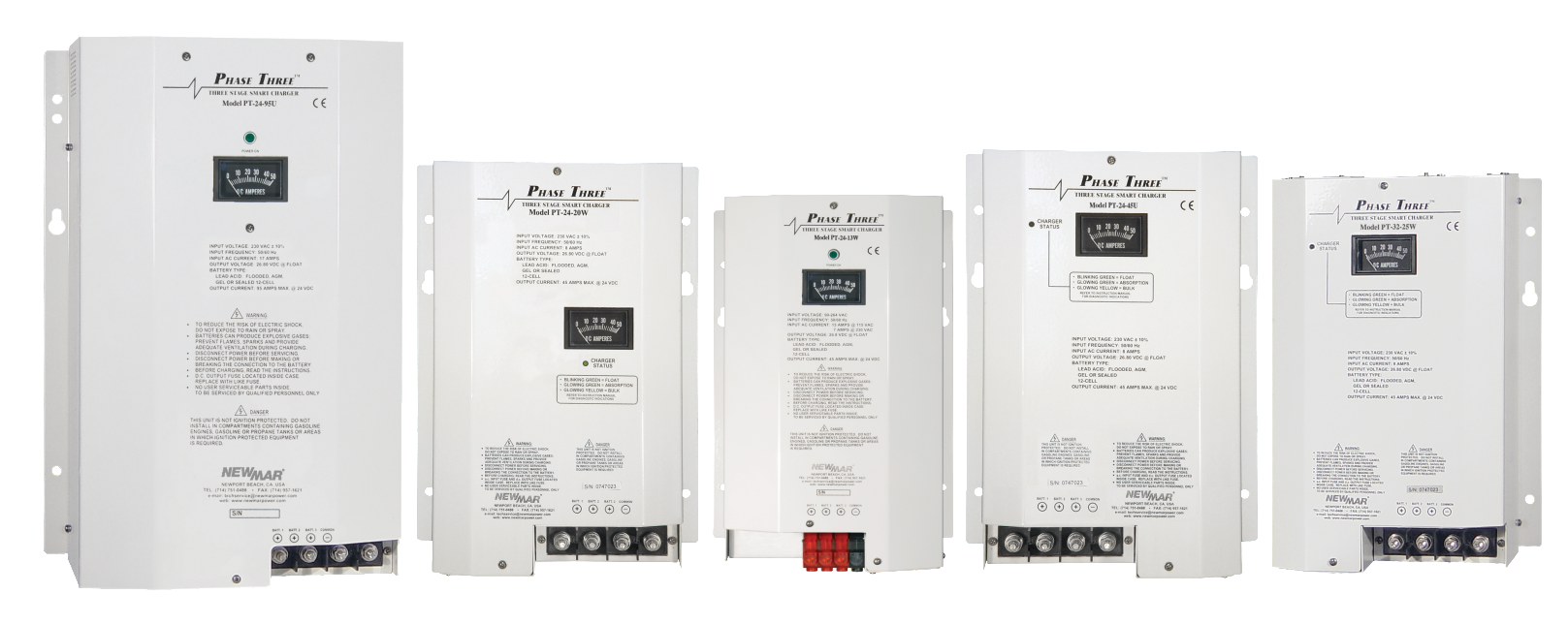
Three Stage “Smart” Chargers
Phase Three “Smart” battery charging technology is now available in a wide range of power levels, allowing you to select the right size, features and flexibility you require for virtually any application from providing quick recharge of auxiliary batteries in vehicles parked in the station house, to powering continuous loads and maintaining peak charge in large battery systems in remote communication sites as well as industrial generator and marine applications. These chargers interact with batteries to put them through the optimum three stage charge process which provides for fastest recovery and ideal conditioning, maximizing battery performance and extending battery life.
A selector switch adjusts output voltage to adapt for gel-cell/flooded lead-acid/AGM battery types. An optional temperature compensation sensor also adjusts output for ideal voltage based on changes in the batteries' ambient temperature. All models are housed in a rugged stainless steel with a durable white powder coat finish, and the internal circuitry is polyurethane coated for maximum corrosion resistance.
[/column]
Features
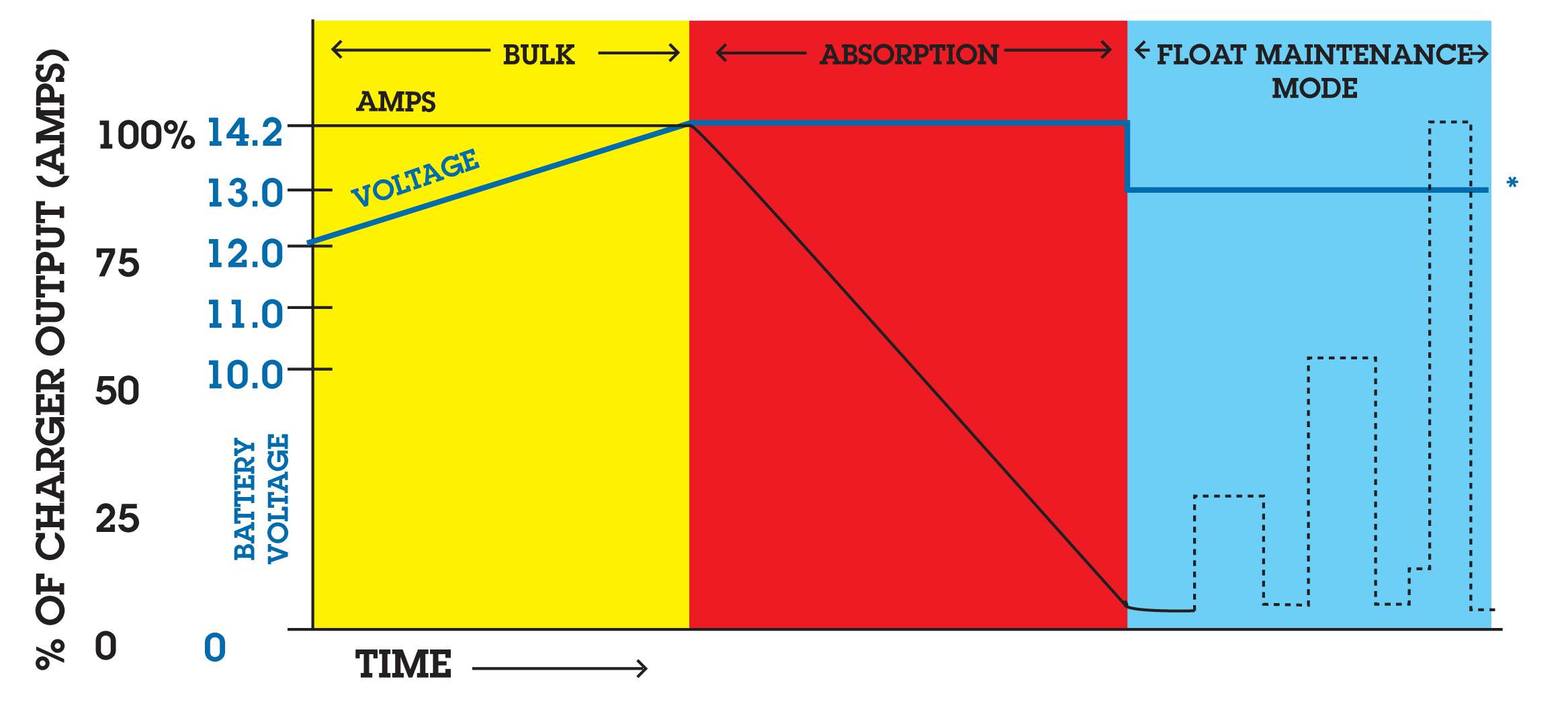
- “Smart” circuitry provides three stage charging—bulk, absorption, float
- Wide model range covers battery system ratings from 14-950 amp-hours
- Gel-Cell/Flooded Lead-acid/AGM battery type switch selects optimum charge/float voltages
- Multiple isolated output banks; ammeter indicates total output current (except PT-7)
- Optional sensor adjusts output voltage based on battery temperature (except PT-7)
- Current limiting-prevents damage from overloading
- Charger status clearly displayed with L.E.D. and/or audible indicators or optional remote panel
- Use as a power supply; can power loads without a battery in line
- Built to last—rugged stainless steel case with a durable white powder coat finish with drip shield and polyurethane coated internal circuitry
- Numerous Safety and EMC Compliances
- Two year parts and labor warranty
Models
| 12 Volt | 24 Volt | 32 Volt |
|---|---|---|
| PT-14W | PT-24-8W | PT-32-25W |
| PT-25W | PT-24-13W | |
| PT-40 | PT-24-20 | |
| PT-80 | PT-24-45U | |
| PT-24-60W | ||
| PT-24-95U |
Specifications
| 12 Volt Models | PT-7 | PT-14W | PT-25W | PT-40U | PT-80 |
|---|---|---|---|---|---|
| Input VAC (50-60 Hz.) |
88-132 or 176-264 |
85-264 | 90-132 or 180-264 |
90-264 | 90-264 |
| Input Amps @ Full Load |
|||||
| @ 115 VAC | 2 | 2.8 | 6.5 | 6.8 | 12 |
| @ 230 VAC | 1 | 1.4 | 4 | 3.4 | 7 |
| P.F. Rating | >.65 | .93@230V .98@115V |
.7 | .98 @ 115V .95 @ 230V |
.95@230V .98@115V |
| Max Output Amps | 7 | 14 | 25 | 40 | 80 |
| Output Banks | 2 | 3 | 3 | 3 | 3 |
| Battery Capacity (Amp-Hours) |
14-70 | 28-140 | 50-250 | 80-400 | 160-800 |
| Operating Temp. Rating Reference |
T-1 | T-2 | T-4 | T-5 | T-7 |
| Case Size Ref. | A-1 | A-2 | A-2 | A-3 | A-5 |
| Weight; Lbs./Kg. | 3.2/1.5 | 8/4 | 8.2/4 | 11/6 | 15.2/7 |
| Optional Temp. Sensor Model |
N/A | TCS-12/24 | TCS-12/24 | TCS-12/24 | TCS-12/24 |
| Remote Panel Model | N/A | RP | RP | EVM-12-2 | RP |
| Equalize Option | No | Yes | Yes | No | Yes |
| Output Indicator Ref. | M-1 | M-3 | M-3 | M-3 | M-3 |
| Compliance Ref. | CG, CE | CG, CE | CG | CG | CE |
| 24 Volt Models | PT-24-8W | PT-24-13W | PT-24-20U | PT-24-45U | PT-24-60W | PT-24-95U |
|---|---|---|---|---|---|---|
| Input VAC (50-60 Hz.) |
85-264 | 90-132 or 180-264 |
90-264 | 90-264 | 207-253 | 90-264 |
| Input Amps @ Full Load |
||||||
| @ 115 VAC | 2.8 | 6.5 | 6.8 | 12 | NA | 26 |
| @ 230 VAC | 1.4 | 4 | 3.4 | 7 | 13 | 14 |
| P.F. Rating | .93@230V .98@115V |
.7 | .98 @ 115V .95 @ 230V |
.95@230V .98@115V |
.7 | .95@230V .98@115V |
| Max Output Amps | 8 | 13 | 20 | 45 | 60 | 95 |
| Output Banks | 3 | 3 | 3 | 3 | 3 | 3 |
| Battery Capacity (Amp-Hours) |
16-80 | 26-130 | 40-200 | 90-450 | 120-600 | 180-950 |
| Operating Temp. Rating Reference |
T-2 | T-3 | T-5 | T-8 | T-6 | T-8 |
| Case Size Ref. | A-2 | A-2 | A-3 | A-5 | A-6 | A-6 |
| Weight; Lbs./Kg. | 8/4 | 8.2/4 | 11/6 | 12.2/6 | 24.1/11 | 24.5/11 |
| Optional Temp. Sensor Model |
TCS-12/24 | TCS-12/24 | TCS-12/24 | TCS-12/24 | TP | TCS-12/24 |
| Remote Panel Model | RP | RP | N/A | RP | N/A | RP |
| Equalize Option | Yes | Yes | Yes | No | No | Yes |
| Output Indicator Ref. | M-3 | M-3 | M-3 | M-3 | M-2 | M-3 |
| Compliance Ref. | CG, CE | CG | CG | EN, CE | EN, CE | EN, CE |
| 32 Volt Model | PT-32-25W |
|---|---|
| Input VAC (50-60 Hz.) |
104-126 |
| Input Amps @ Full Load |
|
| @ 115 VAC | 15 |
| @ 230 VAC | N/A |
| P.F. Rating | .7 |
| Max Output Amps | 25 |
| Output Banks | 3 |
| Battery Capacity (Amp-Hours) |
50-250 |
| Operating Temp. Rating Reference |
T-6 |
| Case Size Ref. | A-4 |
| Weight; Lbs./Kg. | 12.2/6 |
| Optional Temp. Sensor Model |
TP |
| Remote Panel Model | N/A |
| Equalize Option | No |
| Output Indicator Ref. | M-2 |
| Compliance Ref. | EN, CE |
Case Size
| Inches | Centimeters | |||||
|---|---|---|---|---|---|---|
| Ref | H | W | D | H | W | D |
| A-1 | 10.5 | 5.0 | 2.8 | 26.7 | 12.7 | 7.1 |
| A-2 | 12.5 | 7.7 | 4.3 | 31.8 | 19.6 | 10.9 |
| A-3 | 13.85* | 9.5 | 4.8* | 35.2* | 24.1 | 12.2* |
| A-4 | 13.8A | 9.8 | 5A | 35A | 24.9 | 12.7A |
| A-5 | 14.8B | 9.6 | 5.6B | 37.6B | 24.4 | 14.2B |
| A-6 | 17.5C | 12 | 7.2C | 44.5C | 30.5 | 18.3C |
| * Add .75” (1.9 cm) to height and 1.35” (3.4 cm) to depthA Add 1.27” (3.2 cm) to height and 1.1” (2.8 cm) to depthB Add 1” (2.54 cm) to height and .5” (1.27 cm) to depthC Add 2” (5.08 cm) to height and 1” (2.54 cm) to depth | ||||||
Temperature Rating Reference:
| T-1 | -10°C to +45°C; Derate linearly from 100% @ 0°C to 80% @ -10°C |
|---|---|
| T-2 | -10°C to +60°C; Derate linearly from 100% @ 40°C to 60% @ 60°C |
| T-3 | -10°C to +60°C; Derate linearly from 100% @ 50°C to 60% @ 60°C |
| T-4 | -10°C to +60°C; Derate linearly from 100% @ 40°C to 60% @ 60°C |
| T-5 | -20°C to +60°C; Derate linearly from 100% @ 50°C to 75% @ 60°C |
| T-6 | -20°C to +50°C; Full output |
| T-7 | -20°C to +70°C; Derate linearly from 100% @ 45°C to 50% @ 70°C |
| T-8 | -20°C to +70°C; Derate linearly from 100% @ 50°C to 50% @ 70°C |
Output Indicator References
| M-1 | Total output ammeter |
|---|---|
| M-2 | Charge/Float L.E.D. |
| M-3 | Total output ammeter and charger status L.E.D.'s/Alarms |
Compliance References*
See matrix for applicable models
UL UL 1950 (Per DNB report)
CG USCG CFR 183.410 (Ignition protected)
EN EN 60335-1, EN 60335-2-29
CE Carries the CE Mark
* Numerous other Safety and EMC compliances may also apply. Contact factory if further compliance information is required.
Nominal Output Voltages at Gel/Flooded Switch Settings
(Without Temperature Compensation option installed or at 22.2˚C (72˚F) with Temperature Compensation option installed.)
| 12 Volt Models | 24 Volt Models | 32 Volt Model | ||||
|---|---|---|---|---|---|---|
| Charge | Float | Charge | Float | Charge | Float | |
| Setting | @ 50% load | @ .5 amp load | @ 50% load | @ .5 amp load | @ 50% load | @ .5 amp load |
| Gel-Cell | 14.0 VDC | 13.6 VDC | 28.0 VDC | 27.2 VDC | 37.3 VDC | 36.2 VDC |
| Flooded/AGM | 14.2 VDC | 13.4 VDC | 28.4 VDC | 26.8 VDC | 37.8 VDC | 35.7 VDC |
Typical Charging Curve
Temperature Compensation
- 5 mV per cell per ˚C. Sensor supplied with 25' cable and plug-in connector
Protection (all models)
Input/Output Fuses, Current Limiting, Thermal Protection, Forced Air Cooling, Drip Shield
Remote Panel, Model RP
LED's indicate charger output stage. Button allows manual reinitialization of three stage charge cycle. Supplied with 25' cable and plug-in connector. Panel dimensions: 3" H x 4.75" W
Optional Accessories
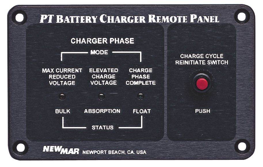
Remote Indicator Panel, Model: RP
(Not available for all models - refer to Specification Matrix above)
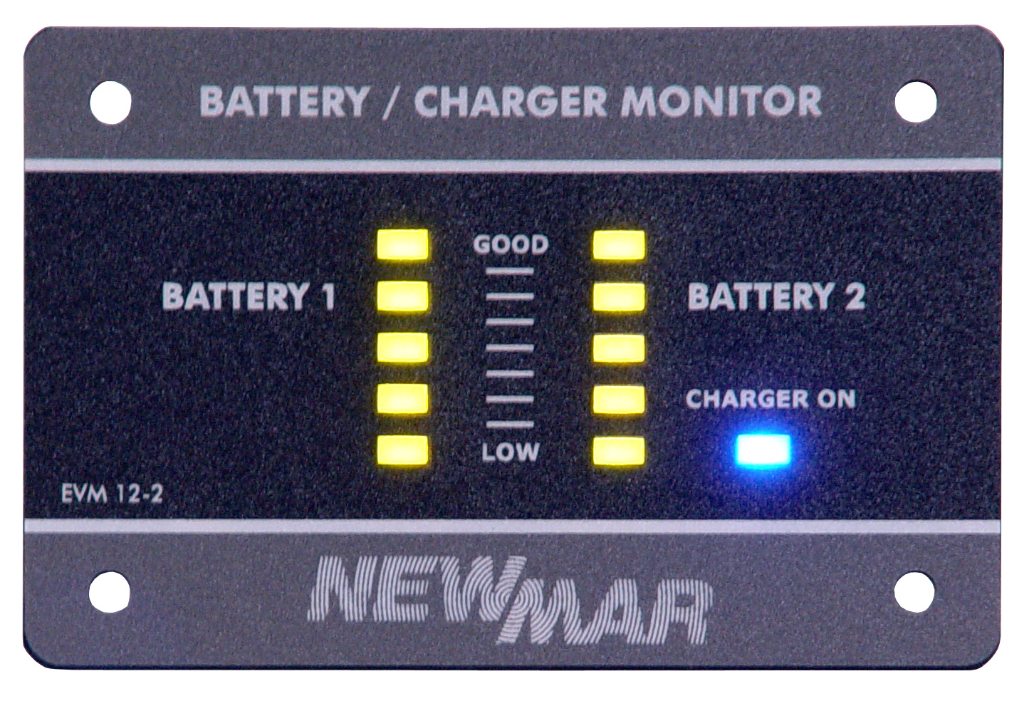
Remote Panel, model EVM-12-2, for us with model PT-40 only
Enables monitoring of when the battery charger is “on” and the batteries’ state of readiness, at a glance of two (2) battery banks only
Temperature Compensation Sensor
Model: TCS-12/24 shown (see Specification Matrix above for applicable sensor depending on charger model)Download Data Sheet (PDF)