
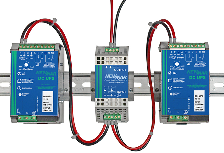
DIN Rail Redundancy Module
For crucial applications where loss of power can be critical or costly it is recommended that two DIN UPS units be paralleled for 1+1 redundancy. However, wiring two DIN UPS in parallel without isolation diodes can result in both units shutting down if one develops a short on the output side, as well as, give false status indicators. To prevent this and provide true isolation and redundancy the DRM-220 DIN-UPS Redundancy Module was developed. The isolation diodes inside the DRM-220 ensure the two DIN UPS units are isolated in the event of a DIN UPS failure, preventing a failed DIN-UPS unit from adversely affecting the other.
Under normal operation, each DIN-UPS supplies approximately 50% of the current required by the load(s). In the event of a DIN-UPS failure, the good DIN-UPS will carry 100% of the load without interruption of power to the load(s), often referred to as a ‘Hot’ switch over. The failed DIN-UPS will reveal its status via its diagnostic LED so the failed unit is easily identified. For additional redundancy, a separate battery is recommended for each DIN-UPS.
This product is UL-2524 certified.

| Model | Input Voltage | Max Output Power | Dimensions (H x W x D) | Weight (Lbs.)/ Unit |
|---|---|---|---|---|
| DRM-220 | 10 - 60V DC | 25 Amps | 4.72" x 1.97" x 1.97" | 1 |
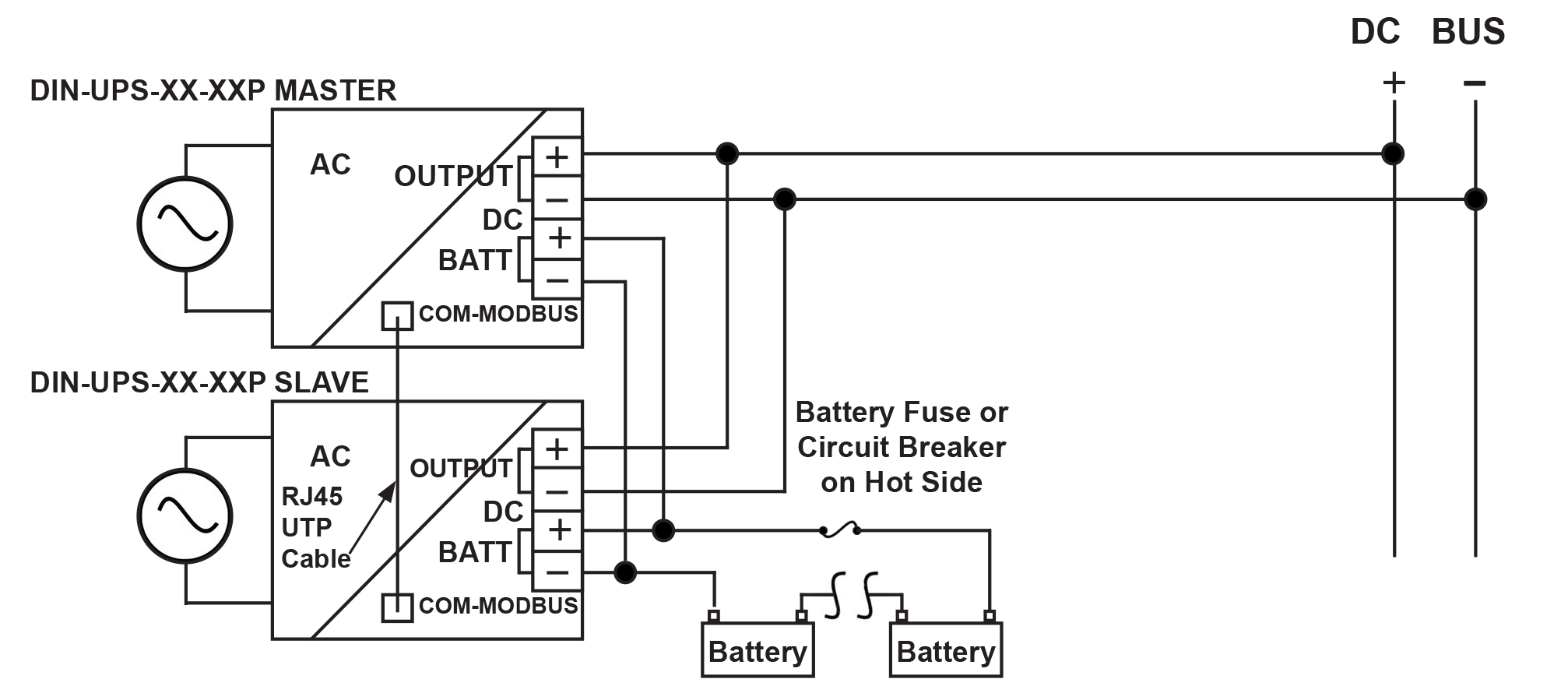
Typical Wiring Diagram: DIN-UPS Redundancy Module
Options
Temperature Compensation Sensor:
P/N 468-5940-0: 3 ft.
P/N 468-5940-1: 10 ft.
RJ45 Patch Cable:
P/N 873-4512-0: 1 ft.
P/N 873-4524-0: 2 ft.
For complete specifications on the DIN-UPS series, refer to DIN-Rail DC UPS series.